- You have no items in your shopping cart
- Subtotal: $0.00
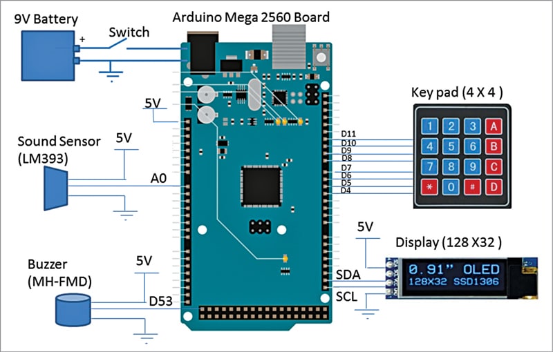
This article describes a Smart Whistle Counter that counts the number of pressure-cooker whistles and the duration of cooking time. It will trigger a buzzer alarm when the preset whistles count or the preset amount of cooking time is reached.
This design can also be used in factories that have boilers with pressure release valves to automatically turn them off when hearing the sound of the boiling point. Or it can be used in steam engines to automatically cut off the power when a sound is made at the ship’s outlet valve.

Additionally, the code can be integrated into metaverse and AR/VR environments for gesture-based control.
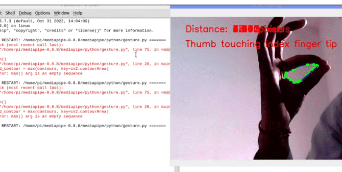
Join us as we explore the exciting possibilities of gesture-based control for a more intuitive and immersive home automation experience.
So let’s start the project with a collection of the following components-
Bill of Materials
| Components | Quantity | Description | Price |
| Raspberry Pi 4 | 1 | SBC 1GB RAM | 4000 |
| 5V Relay Module | 1 | 5V AC SPST | 50 |
| RPi camera | 1 | CSI Ribbon | 300 |
| Total | 4350 |
Code for Gesture Controller
To recognize the hand and fingers, calculate the distance between fingertips, and detect gestures, we can employ two different approaches-
The first approach uses Numpy and OpenCV, while the second combines OpenCV with Mediapipe.
Although the Mediapipe-based system is accurate and efficient, the library may have installation issues. For now, we will focus on using OpenCV exclusively for coding purposes.
However, we plan to update this project in the next version by incorporating Mediapipe.
First, you must install OpenCV and Numpy on your Raspberry Pi using the Linux terminal. Execute the following commands:
sudo pip3 install opencv
sudo pip3 install numpy
Once the installation is complete, you can proceed with the code implementation.
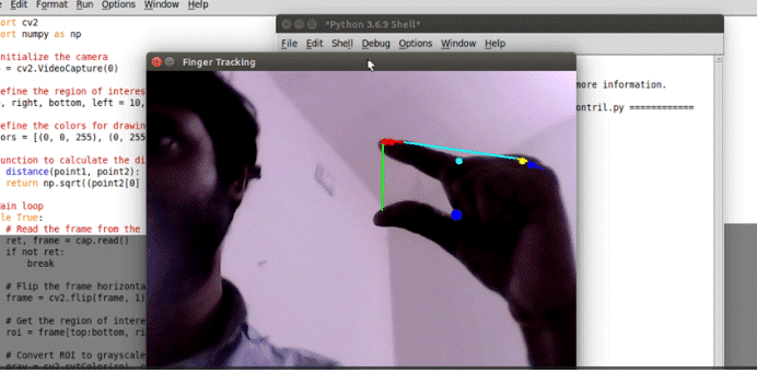
First, import the OpenCV and Numpy libraries. Then, utilize the gpiozero library to control the GPIO pins on the Raspberry Pi. Assign the appropriate LED number to control the light based on finger movements. Next, capture the frames in the code.
Afterward, process the video frames to detect the hand and fingers. Use an if condition to determine the distance between the index and thumb fingers. If the thumb and index finger touch each other, set a function to turn the lights on.
Gesture Controller Circuit Diagram
To connect the relay to your Raspberry Pi, follow these steps:
- Locate the 5V and GND pins on the Raspberry Pi. Connect the corresponding pins of the relay to these pins. The 5V pin provides power to the relay, while the GND pin establishes the ground connection.
- Choose a free pin on the Raspberry Pi for relay control. In this example, we’ll use pin 17, but you can use any available pin that suits your needs.
- Connect the input pin of the relay to pin 17 on the Raspberry Pi. This pin will control the relay’s state.
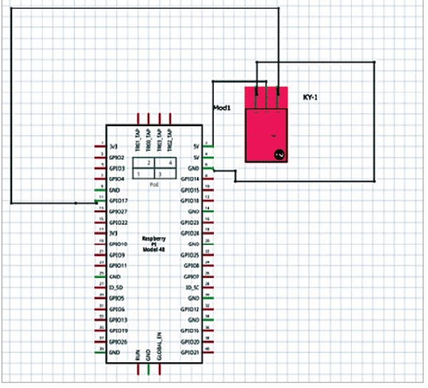
Make sure to refer to the circuit diagram for a visual representation of the connections. Remember that you can use any free pin on the Raspberry Pi for relay control, not just pin 17.
Testing and Working
To test the code, follow these steps:
- Run the code you have implemented.
- Position your finger in front of the Raspberry Pi camera.
- Move your fingers and touch your index finger to your thumb.
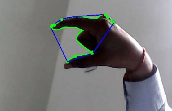
If the code functions correctly, touching the index and thumb fingers should activate the relay, turning it on. However, please note that finger and palm detection accuracy may not be optimal since you did not utilize any machine learning (ML) models in the current implementation.
To enhance the accuracy of finger and palm detection, consider updating the project by incorporating Mediapipe. Mediapipe provides robust ML models for hand and gesture recognition, leading to improved accuracy in detecting fingers and palm positions.

[ad_2]


